
3D printing tolerances for shafts and bearings: clearance, press fit and test prints
Printed hole sizes for Ø8 and Ø6 shafts, 688 bearings and LM6UU bushings, clearance vs press fit, teardrop holes for horizontal bores and how to print a tolerance test.
Published
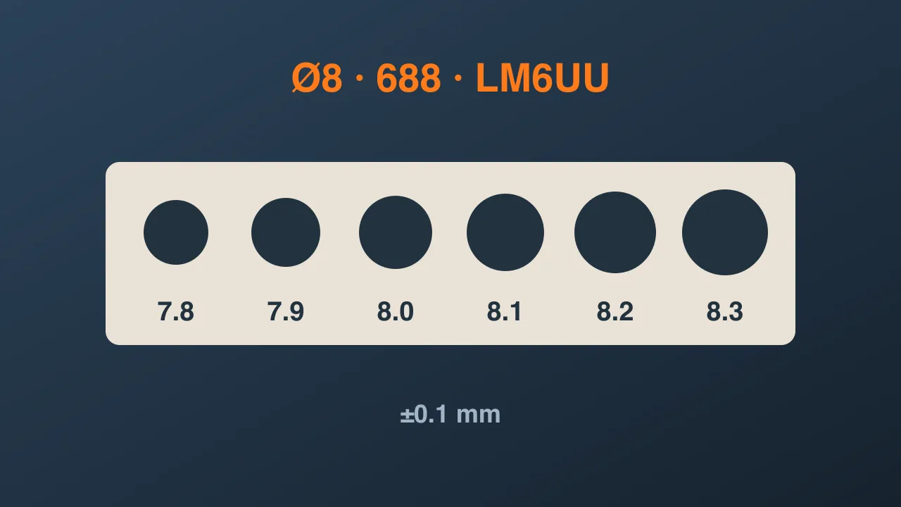
Draw a Ø8 hole in CAD, print it, and an 8 mm shaft usually will not fit. Extruded plastic bulges slightly, printed holes come out a bit smaller than drawn, and every printer is off in its own way. This post lists the hole sizes FoxBench DIY uses for shafts and bearings, and how to find the right numbers for your own printer.
Three kinds of fit
| Fit | Use it when | Hole vs. shaft |
|---|---|---|
| Clearance | Shaft turns or slides in the hole, comes out easily | 0.2–0.3 mm larger |
| Press fit | Shaft stays put without glue, needs a light tap | Same size to 0.1 mm smaller |
| Hand press | Bearings, bushings: push in by hand, does not fall out | 0.1 mm larger |
Sizes in use
Measured on an FDM printer, PLA, 0.4 mm nozzle, holes printed vertically (hole axis perpendicular to the bed):
| Part | Actual size | Printed hole |
|---|---|---|
| Ø8 stainless shaft, clearance | Ø8 | Ø8.2–8.3 |
| Ø8 stainless shaft, press fit | Ø8 | Ø7.9–8.0 |
| 688 bearing (8×16×5), hand press | Ø16 outer | Ø16.1 |
| LM6UU bushing (Ø6 shaft, Ø12 outer) | Ø12 outer | Ø12.1–12.2 |
| M3 brass insert (4.5 outer) | Ø4.5 | Ø4.0 (see the heat-set insert guide) |
These are starting points. Your printer may be off by ±0.1 mm, so print a test before a big part.
Horizontal holes: use a teardrop
When a hole lies horizontally (hole axis parallel to the bed), the top half is an overhang with nothing underneath. The plastic sags, making the hole distorted and smaller at the top.
The fix: draw the hole as a teardrop with the top pointing up at 45°. Printers handle 45° without supports, the bottom half stays round and the shaft still fits under the point. The channel’s turntable uses teardrop holes for its horizontal roller axles.
Holes at the bed: watch for elephant’s foot
The first layer is usually squashed and spreads out (elephant’s foot). Vertical holes that start at the bed therefore narrow in the first 0.2–0.4 mm. Two fixes:
- Chamfer the bottom edge of the hole by 0.5 mm in CAD.
- Or enable elephant foot compensation in the slicer.
How to print a tolerance test
- Draw a 6–8 mm plate with a row of holes 0.1 mm apart, for example 7.8 / 7.9 / 8.0 / 8.1 / 8.2 / 8.3 for an 8 mm shaft. Emboss the size next to each hole.
- Print it with the same filament and settings you will use for the real part (layer height, perimeters, temperature). New filament means a new test.
- Try each hole with the real shaft and bearing and pick the one that gives the fit you need.
- Store the result as a parameter in your CAD (for example
rod_d,brg_pocket_d) so every later part uses it.
A test takes a few minutes and a few grams of filament: much cheaper than a failed six-hour print.